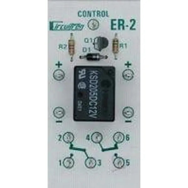
Circuitron 5624 ER-2 External Relay
Circuitron 5624 ER-2 External Relay is backordered and will ship as soon as it is back in stock.
Couldn't load pickup availability
Description
Description
Circuitron 5624 ER-2 External Relay
Circuitron ER-2 External Relay DPDT ~ 5624
The CIRCUITRON ER-1 and ER-2 are circuits consisting of a 2 amp
relay, either single pole double throw in the case of the ER-1, or double pole double throw in the case of the ER-2, and all the necessary driver circuitry to enable them to be directly connected to the output of any CIRCUITRON Detection Units. The relay contacts can be used to control AC or DC circuits and are ideal for use with CIRCUITRON Block Occupancy Detectors to provide automatic train control. Both the ER-1 and the ER-2 have 12 volt relays and require a supply voltage of 11 to 14 volts DC. The ER-1 and ER-2 present a negligible load on the Detection Unit to which they are connected as the control current is only around 2 milliamps.
INSTRUCTIONS: The ER-1 and ER-2 can be connected with .110″ solderless connectors or by soldering leads directly to the terminals on the printed circuit board. If soldering, use a small penciltype iron and electronics-grade rosin core 60/40 solder (available at Radio Shack). Use only as much heat as necessary to obtain a good joint and do not wiggle the terminal until the solder has cooled completely.
1) Mount the circuit board in a convenient location. The mounting pads on the corners of the boards may be drilled out, or a section of CIRCUITRON’s Printed Circuit Mounting Track (PCMT) may be used for the simplest mounting.
2) Connect the supply terminals [+] and [-] to a source of 11 to 14 volts DC. This should be the same power supply you are using for your Detection Units. WARNING: Never connect AC power to the [+] and [-] terminals. Damage to the control transistor is likely and is not covered under our warranty.
3) Connect the Control Terminal [CONTROL] to the output of one of CIRCUITRON’s Detection Units. (The Detection Unit used will depend on the application.)
4) Connect the devices to be controlled to the contact terminals on the circuit boards. These terminals are numbered and connect through the relay contacts as follows:
ER-1: Terminal [2] is connected to Terminal [3] when the output of the Detection Unit is off. When the output is on, the relay will pull in, and Terminal [2] will be connected to Terminal [1].
ER-2: When the output of the Detection Unit is off, Terminal [3] will be connected to Terminal [2] and Terminal [4] will be connected to Terminal [6]. When the output of the Detection Unit turns on, the relay will pull in, and then Terminal [3] will be connected to Terminal [1] and Terminal [4] will be connected to Terminal [5].
Specifications
Specifications
-
Scale-
-
Product Type-
-
Height
-
Width
-
Depth


